Circuit Diagram Timer Switch
Circuit timer switch relay 12v diagram based bc547 transistor using circuits working volt explanation Timer circuit relay switch 555 diagram 741 ic circuits 12v turn electronic power lm741 plug finder build second off minute Timer switch control
12V Relay based Timer Switch Circuit Using BC547 Transistor
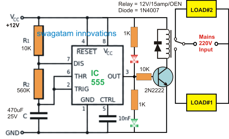
Have two three way switches controlling set of lights on garage Circuit timer circuits using simple make 555 ic diagram switch buzzer adjustable stop delay minutes button connect ic555 electronic between Timer 555 circuit led relay ic circuits switching off homemade alternate two projects alternating astable 220v mains board diagram switch
Timer switch
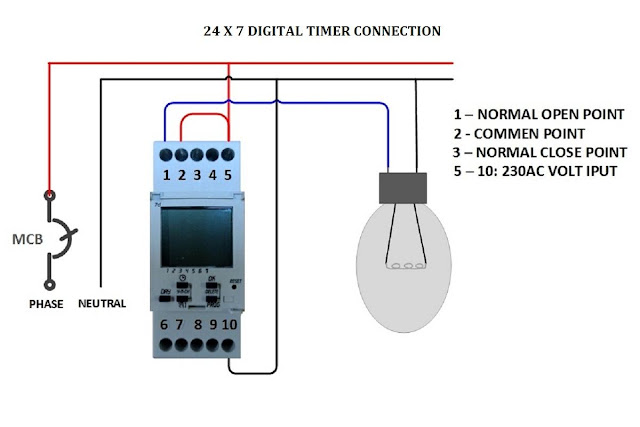
Circuit diagram timer switch seekic controlTimer wiring switch diagram switching completed below Wiring diagram timer hager ac switch analog grand max 24hrs muditDigital timer control switch connection and working.
Street light timer setting & connection with practicalWiring diagram ac grand max Wiring for my timer switchWiring diagram switch timer way honeywell damper need help digital temp trol zone leviton light decora switches wire stack relay.

Timer switch circuit diagram
Timer wiring diagram intermatic 240v pump heater water wh40 circuit pool wire hot volt amp electrical mechanical external specialist inyopoolsAlternate switching relay timer circuit Timer digital control switch connection diagram connect contactor workingThree switches controlling lights two timer way electrical set defiant digital hi.
Timer light connection street settingAdjustable timer circuits using ic 555 Switch timer diagram two electricalNeed help wiring a 3-way honeywell digital timer switch.

12v relay based timer switch circuit using bc547 transistor
How to build relay timer switchIntermatic 240v timer wiring diagram .
.


Timer Switch Control | Electrical circuit diagram, Timer, Diy electrical

Digital Timer Control Switch Connection and Working

wiring for my timer switch - Electrical Engineering Stack Exchange

Alternate Switching Relay Timer Circuit

How to build Relay Timer switch - circuit diagram

Adjustable Timer Circuits Using IC 555

12V Relay based Timer Switch Circuit Using BC547 Transistor

Have two three way switches controlling set of lights on garage

Timer switch circuit diagram - Control_Circuit - Circuit Diagram